VPC Peering for multiple Zadara Edge Clouds
Note
For VPC Peering between zCompute VPCs in the same Zadara Edge Cloud, use zCompute’s built-in VPC Peering Connection (same cloud) solution.
For VPC Peering between zCompute VPCs in different Zadara Edge Clouds, or zCompute VPC to customer on-premises peering, use the VPC Peering for multiple Zadara Edge Clouds solution that leverages open-source pfSense software.
VPC Peering for Zadara Edge Clouds enables routing network traffic between two VPCs, using private IPv4 addresses.
This implementation uses IPSec technology for securing private connections between instances communicating with each other in a Zadara Edge Cloud.
Introduction
Virtual Private Cloud (VPC)
A virtual private cloud (VPC) is a virtual network dedicated to your Zadara Edge Cloud account. It is logically isolated from other virtual networks. You can launch virtual machines running computing workloads into your VPC.
The VPC model allows a user in a multi-tenant environment to make use of advanced networking capabilities and services for microsegmentation, isolation and routing.
zCompute VPC Peering
A VPC Peering connection is a networking connection between two VPCs that enables routing network traffic between them using private IPv4 addresses. Instances in either VPC can communicate with each other as if they are within the same network. Zadara Edge Cloud uses the existing infrastructure of a VPC to create a VPC Peering connection.
A VPC Peering connection helps you to facilitate the transfer of data. When you establish peering relationships between VPCs across different Zadara Edge Clouds, resources in the VPCs in the different edge clouds can communicate with each other using private IP addresses, without using a gateway, VPN connection, or network appliance. The traffic remains in the private IP space. All inter-cloud traffic is encrypted by IPSec.
Leveraging zCompute capabilities, Zadara offers self-managed VPC Peering, based on the open-source pfSense software.
zCompute VPC Peering supports the following use cases:
VPC to VPC
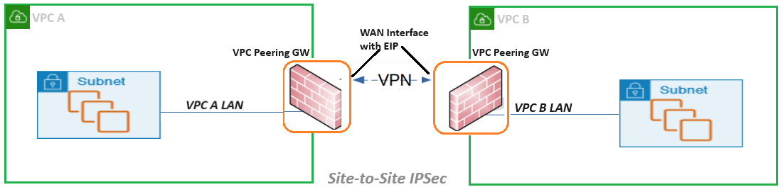
For the VPC to VPC use case implementation, the VPC Peering Gateway (GW) image in zCompute’s Marketplace should be deployed on instances allocated on a VPC that need peering connectivity. The VPC Peering GW implements Firewall (FW) functions between the internal VPC subnet and the external public WAN. The VPC Peering GW is attached to the internal VPC subnet and external WAN subnet. It has capabilities for managing access and pass-through rules over FW. The WAN interface of the VPC Peering GW associated with an Elastic IP (EIP) and used for Site-to Site IPSec VPN, provides highly secured private connectivity between VPCs. The same architecture is used for multi-point VPC Peering supporting full mesh topologies between multiple VPCs.
VPC to on-premises
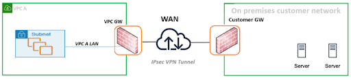
The VPC to on-premises use case implementation enables secure connectivity from a VPC to a customer’s on-premises data center and internal network. The deployment of VPC to on-premises peering is achieved by an IPSec tunnel between the VPC Peering GW on a Zadara Edge Cloud and the FW installed on a customer network GW.
VPC Peering GW Deployment
The deployment workflow for VPC Peering is based on pfSense software.
Deployment Requirements
X86-64 Instance
1 vCPU
2GB RAM
8 GB disk drive
2 NICs (WAN and LAN)
EIP on WAN interface
There is no overlapping CIDR between peered VPCs.
A zCompute VPC configured with Public and Private Subnets.
Deployment Workflow
Note
The initial deployment flow is identical for both VPC Peering for multiple Zadara Edge Clouds and for VPN Service for Zadara Edge Clouds.
The following workflow must be run on a VPC GW instance that is configured with:
Public and Private Subnets
A Security Group preconfigured for this deployment. See the section on Security Hardening at the end of this page.
A preloaded image is available in the zCompute Marketplace, and provides an easy to use pfSense OpenVPN deployment option.
Download the pfSense image from Marketplace
In the zCompute UI, go to Machine Images > Marketplace and select the pfSense-CE (VPC Peering GW) image.
Set the Scope to Project or Account, and download the image.
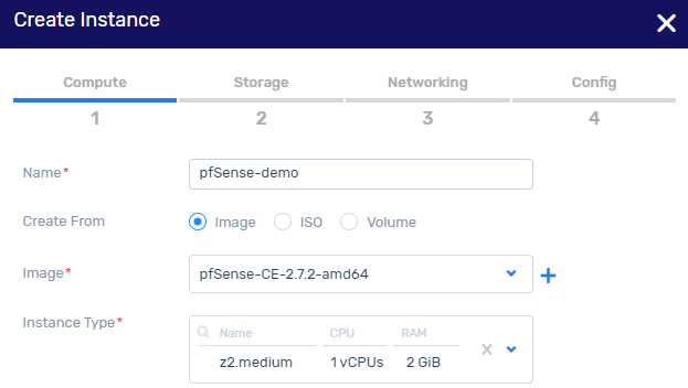
Create an instance based on the pfSense image
In Machine Images > Images, select the VPC Peering GW (pfSense-CE) image.
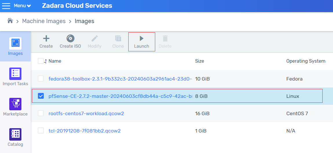
Click Launch to create an instance with 2 subnets.
One subnet is for the internal VPC LAN. The other subnet will be used for the public-facing WAN interface.
In the Storage tab, accept the default settings. Click Next.
In the Networking tab, configure the public subnet.
On completion of the public subnet configuration, click Add to configure the private subnet.
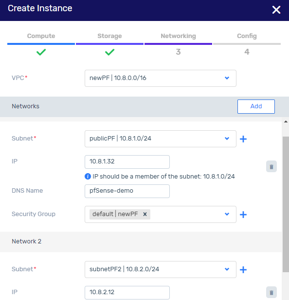
Note
The significance of first configuring the public subnet followed by the private subnet is so that the public subnet should be associated with eth0, and the private subnet associated with eth1.
Networking configuration for the pfSense instance
Go to Compute > Instances and select the instance.
In the instance’s lower pane, click the Networks tab.
Attach an Elastic IP to the public subnet:
Click the row of the public subnet.
In the lower menu, select More > Attach Elastic IP. Attach an Elastic IP to the NIC attached to the WAN/public subnet, for example eth0.
The Elastic IP will be used for the WAN interface on the VPC GW.
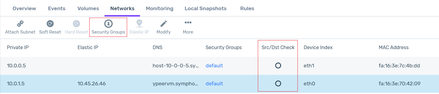
For each of the eth0 and eth1 interfaces (both the public and private subnets), disable the Src/Dst Check:
In the instance’s Networks tab in the lower pane, click the network interface row.
Click Security Groups. In the Security Groups modal that opens, uncheck the Source/Destination checkbox, and save the configuration.
Networking setup on the pfSense VM
Connect to the VM VNC to set up the networking configuration.
Go to Compute > Instances > [VM instance name] > Connect.
The VNC window opens, and the pfSense menu displays:
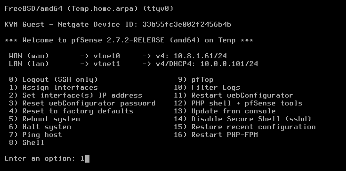
From the menu, select option 1: Assign interfaces:
Note
There is no need to set up VLANs.
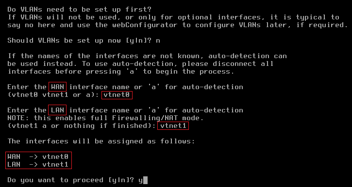
Set up vtnet0 for WAN (mapped to eth0 on the VM instance).
Set up vtnet1 for LAN (mapped to eth1 on the VM instance).
After assignment of the network interfaces, the pfSense menu reappears.
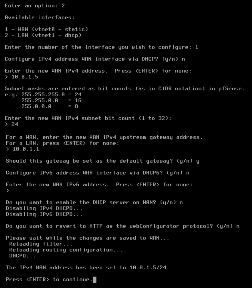
From the menu, select option 2: Set interface(s) IP address.
Setup the WAN to static IPv4.
For example:
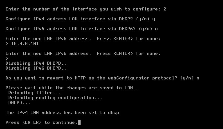
Set up the LAN interface with IPv4 DHCP.
For example:
On completion of the IP setup, the updated WAN and LAN IP assignments display, followed by the pfSense menu.
Note
The deployment flow up to this step is identical for both VPC Peering for multiple Zadara Edge Clouds and for VPN Service for Zadara Edge Clouds.
Sign on to the pfSense web client to continue the specific deployment implementation.
In a browser window, launch the pfSense web client using the Elastic IP assigned earlier to the public subnet. For example,
https://10.41.31.5.The pfSense web client’s default credentials:
username:
adminpassword:
pfsense
Note
The recommended best practice is to change the pfSense admin password at the first sign-on to the pfSense web client.
IPSec VPN setup
Important
This procedure involves configuration on 2 sites.
Ensure that you complete the setups and bring up pfSense instances on both VPCs.
Set up a site-to-site IPsec tunnel according to the comprehensive step by step IPsec Site-to-Site VPN Example in the pfSense user guide.
Routing configuration:
On both sides of the IPsec tunnel, there is the need to define static routes to the remote VPC:
To define a static route over IPSec tunnel on the pfSense FW:
In the pfSense web client, navigate to System > Routing > Static Routes.
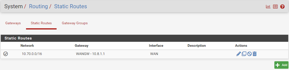
Click Add below the Static Routes table.
In the Edit Route Entry form, enter:
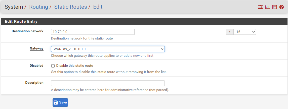
Destination network: CIDR of the destination VPC.
Gateway: Select the WAN GW of the pfSense instance.
Click Save.
In the Static Routes screen, click Apply Changes.
In zCompute, add the route to the remote VPC CIDR with the GW Network Interface allocated for the WAN port on the pfSense instance:
Navigate to VPC Networking > Route Tables, and click the route table associated with the VPC.
In the VPC’s lower menu Route tab, click + Create.
In the Create Route dialog, enter:
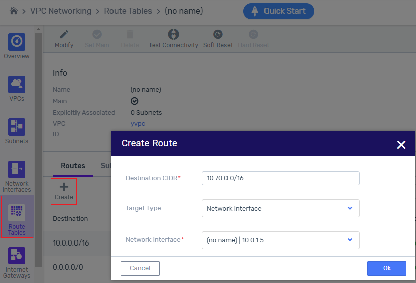
Destination CIDR: CIDR of the destination VPC.
Target Type: Select Network Interface from the dropdown, to display the Network Interface input prompt.
In the Network Interface prompt, select the GW Network Interface allocated for the WAN port on the pfSense instance.
Click Ok to save.
Important
In the destination’s pfSense web client and zCompute VPC Route Tables screen, repeat this procedure for the reverse direction.
Security hardening configuration
Change default passwords to non-default ones.
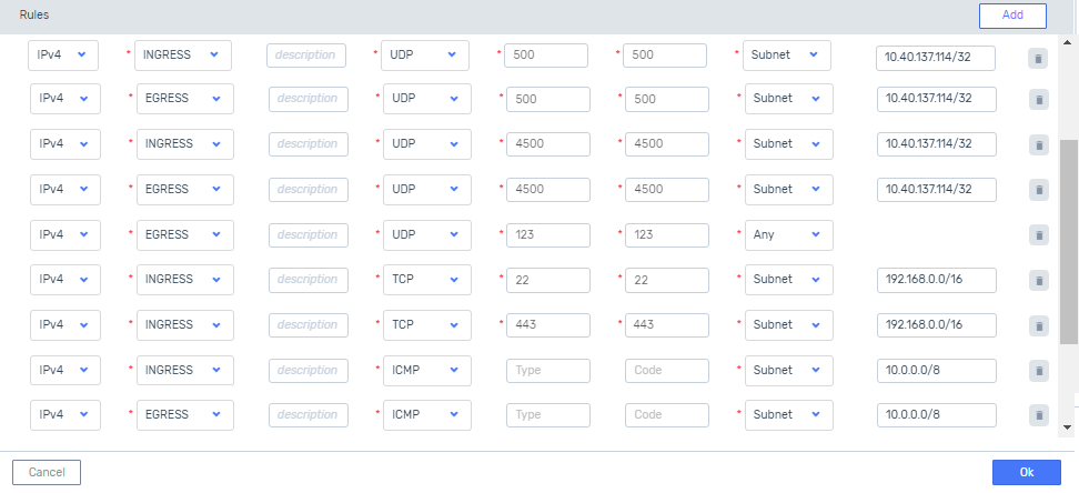
Update the VPC Security Group to block non-essential ports.
The VPC Peering GW requires the following ports for normal operations:
UDP ports 500 and 4500 for IPSec
The Subnet Remote Value on these ports must be set to the EIP of the destination VPC’s Peering GW.
UDP port 123 for NTP
TCP ports 22 (SSH) and 443 (HTTPS) for managing the pfSense virtual appliance
These ports can be blocked when the configuration is complete.
ICMP for troubleshooting
This configuration can be blocked when troubleshooting is complete.
Additional ports might be needed for applications running on VPC VM instances.
Important
In the destination zCompute VPC’s Security Group screen, repeat this configuration for the reverse direction.